With proper grounding in your Rock Island house, you reduce the risk of electrical shock and house fires, protect appliances from surges, and ensure code-compliant, reliable systems; when you verify grounding and address faults promptly, you preserve your family’s safety and extend equipment life while minimizing costly repairs.
Why Proper Grounding Matters in Rock Island Houses
If your Rock Island home has older wiring or ungrounded two‑prong outlets, a proper grounding system gives fault current a low‑impedance return so breakers and fuses clear quickly, limiting voltage on exposed metal. You’ll reduce stray voltages on plumbing and cable shields, protect 120/240 V, 60 Hz circuits from sustained overvoltage, and help whole‑house surge arrestors divert transient energy away from sensitive electronics, lowering both shock and fire risk.
Protecting occupants from electric shock and fire
You should have bonding and grounding that ties metal boxes, water pipes, and service equipment together so a ground fault creates a predictable path and trips protective devices. Installing GFCIs in kitchens, bathrooms, and outdoor receptacles prevents many contact shocks by detecting imbalance and tripping in milliseconds, and proper bonding of gas and water lines reduces the chance of dangerous touch potentials that can spark electrical fires.
Preventing equipment damage and nuisance tripping
You can avoid repeated nuisance trips and premature equipment failure when grounding stabilizes reference voltages for electronics and provides a low‑impedance route for transient energy. Pairing a solid electrode system with whole‑house surge arrestors and point‑of‑use surge suppressors prevents line transients from stressing motor start capacitors, power supplies, and HVAC controls, reducing service calls and replacement costs.
For example, transients from utility switching or nearby lightning can reach several kilovolts and puncture capacitor dielectrics or semiconductor MOVs in surge protectors; you’ll see failed compressors and ruined control boards without effective diversion paths. Test grounding and bonding connections, use coordinated surge protection (service and branch‑level), and replace damaged MOVs to keep HVAC compressors, refrigerators, and smart home devices functioning reliably.
Local factors affecting grounding in Rock Island
You must account for local variations when sizing and installing a grounding system in Rock Island; soil conductivity, seasonal water table swings, and nearby industrial or river influences change performance. Typical Midwest values range from 20-1,000+ ohm·m depending on clay versus sand content, and clay-rich pockets lower rod depth needs. Common remedies include multiple rods, conductive backfill, or chemical electrodes. After you evaluate site-specific resistivity and contamination you can prioritize fixes that will lower your grounding resistance.
- Soil type
- Moisture / water table
- Corrosion risk
- Proximity to river / industrial sites
Soil type, moisture, and seasonal water table
You’ll find that clay layers in Rock Island typically yield low resistivity (~20-200 ohm·m) while sandy fills can exceed 1,000 ohm·m, forcing deeper or more numerous electrodes. In spring the Mississippi’s influence can raise the water table by several feet, improving conductivity; in late summer drought can double resistivity locally. You should plan for 8-10 ft rod depths or chemical electrodes in high-resistivity zones and verify with a two- or four-point resistivity test.
Corrosion, freeze/thaw cycles, and proximity to river/industrial sites
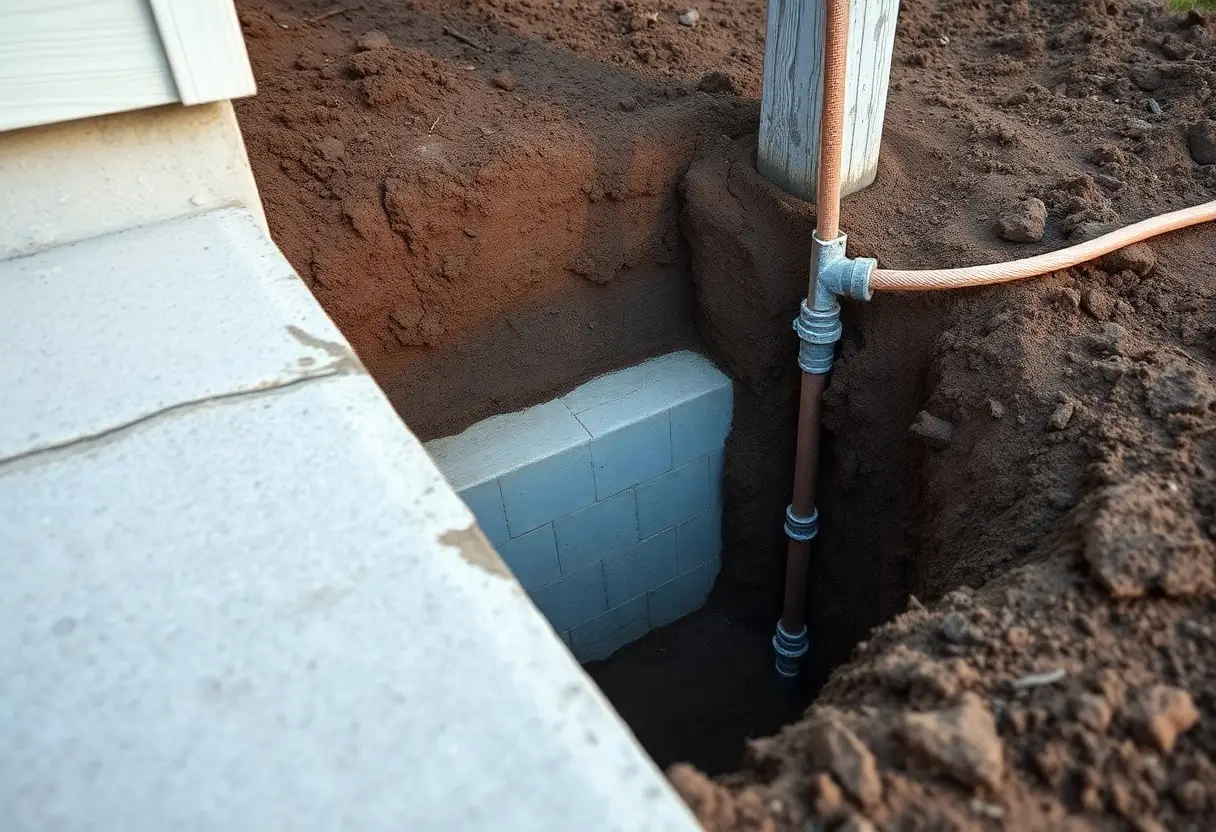
Your grounding materials face accelerated degradation near the river or industrial sites where chlorides and sulfates are present; aggressive soils can corrode steel at about 0.1-0.5 mm/year. Freeze/thaw movement can loosen clamps and raise electrode resistance if rods aren’t below the frost line (~3 ft (36 in)). You should schedule at least an annual inspection and electrical retest after major seasonal shifts.
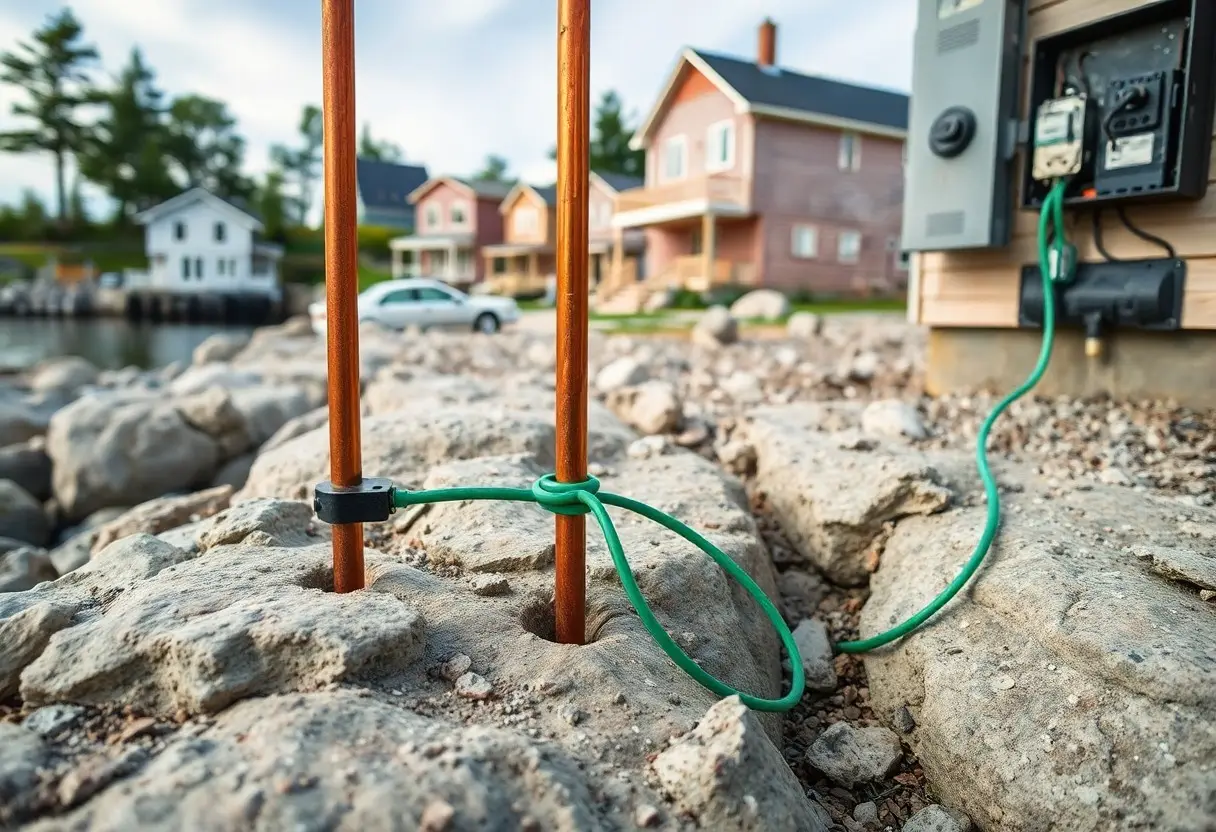
In practice, mitigate those risks by using copper-bonded 8 ft rods, exothermic welds for permanency, and conductive backfill like bentonite around rod interfaces; contractors in Rock Island often replaced corroded iron rods with copper-bonded rods and achieved system resistance under 25 Ω within a day. When industrial effluents or river salts are present, consider cathodic protection for buried metallic components and use corrosion coupons or periodic close-interval surveys to quantify metal loss-sites with measured corrosion rates above 0.2 mm/year should move to stainless connections or sacrificial anodes. Finally, record fall-of-potential tests and clamp readings every 2-3 years and re-torque or replace hardware after freeze/thaw cycles to keep your grounding reliable.
Common grounding deficiencies in Rock Island homes
Missing, undersized, or corroded grounding electrodes
Homes you see in Rock Island often lack a proper electrode or have one that’s failed: old iron water-pipe electrodes corroded after 40-80 years, or absence of an 8‑foot copper‑clad rod at detached garages. Undersized grounding conductors (for example, 8 AWG where a heavier conductor is needed) and rusted clamps reduce fault-current paths, raising the chance of electric shock, equipment damage, or fire. You should verify electrode condition and conductor sizing with testing and repair by a licensed electrician.
Improper bonding, shared neutrals, and DIY fixes
Incorrect bonding between your service, water, gas, and cable systems is common, and DIY attempts often make things worse: a shared neutral on a multi‑wire branch circuit tied without a tied breaker can carry excessive current, overheating insulation and creating a fire or shock hazard. You may spot neutrals double‑tapped on breakers or jumper clips removed-these shortcuts defeat protective coordination and can leave metal piping or enclosures at dangerous voltages.
Further detail: bonding must create a single, low‑impedance path back to the service so fault current trips breakers; gas piping missing a proper bonding jumper or MTU cable not bonded are frequent finds. Multi‑wire branch circuits require a common trip or handle‑tied breakers so the shared neutral isn’t overloaded during maintenance. DIY fixes like splicing neutrals or using makeshift clamps often violate code and leave you exposed-corrective work usually means installing proper 4‑wire feeds, common‑trip breakers, and correctly sized bonding jumpers.
Safety codes and regulatory requirements
Your local code enforcement ties grounding practices directly to life-safety and insurance compliance, so you must follow the adopted NEC edition and municipal amendments when upgrading or repairing. Inspectors focus on service bonding, electrode installation, and routed grounding electrode conductors; missing bonds or open equipment grounding conductors are common failures that increase fire and shock risk and can lead to permit denial or insurance claims being voided.
Relevant NEC provisions and typical local amendments
NEC Article 250 governs grounding and bonding-pay particular attention to 250.52 (types of electrodes), 250.66/Table 250.66 (GEC/bonding sizes), and 250.32 (separate structures). Many jurisdictions in the Midwest adopt the 2017-2023 NEC with amendments that often mandate a minimum 6 AWG copper grounding electrode conductor for typical 100-200 A services and require bonding to metallic water service and concrete-encased (Ufer) electrodes when present.
Permit, inspection, and licensed electrician considerations
You need a permit for service changes, panel swaps, new feeders, and most grounding modifications; inspections usually include rough (before concealment) and final checks. Municipalities expect a licensed electrician‘s signature on plans, and unpermitted or improperly bonded work can trigger rework orders, fines, or insurance issues, so you should hire a licensed pro for service-side grounding and bonding.
When you engage a licensed electrician, they will submit a permit application with conductor sizes, electrode locations, and bonding details; typical permit turnaround is about 3-10 business days, while inspection scheduling is often within 24-72 hours after request. Expect to show the rough inspection before you close walls and a final inspection after meter or panel installation; keep contractor license numbers and inspection reports for real estate disclosure and insurance records.
Inspection and testing procedures
You should inspect grounding after renovations, flooding, or every 1-3 years depending on soil chemistry and age; start by checking visible connections, then proceed to measured tests. Use a multimeter, clamp-on ground tester, and a portable GFCI tester to verify continuity and protective device operation. If you find open continuity, heavy corrosion, or ground resistance above 25 Ω, schedule corrective work immediately and document readings for code compliance and future reference.
Visual inspection checklist for grounding and bonding
Walk every accessible connection and look for loose clamps, paint-covered contacts, broken conductors, and missing bonding jumpers at water meters and gas lines. Confirm that ground rods are exposed and that clamps are tight and corrosion-free. Verify evidence of multiple rods where required and that panel neutrals and grounds are properly separated in subpanels. Photograph defects and tag locations for prioritized repair.
Diagnostic tests: continuity, ground resistance, and GFCI/RCD verification
Start with a continuity test between the service equipment and electrode – values under 1 Ω are ideal; follow with a clamp-on ground resistance test (or fall-of-potential if you can disconnect) aiming for ≤25 Ω. Test GFCI/RCDs with a 5 mA trip tester and verify trip times; a device that fails to trip or shows high resistance needs immediate action. Log all measurements and compare to NEC/IL code expectations.
For deeper accuracy, use a three-point fall-of-potential test when permitted: place P and C probes at prescribed distances (10-50 m ranges work well for typical yards) and record multiple readings to average out soil variability. Use a low-resistance ohmmeter for panel-to-electrode continuity – readings above a few ohms often indicate corroded clamps or severed conductors. In one Rock Island inspection a clamp-on reading of 120 Ω dropped to 8 Ω after adding a second rod and replacing corroded connectors, showing how targeted fixes restore protection.
Remediation and best practices
Begin remediation with a full site assessment: perform a three‑point ground resistance test and a continuity check on your bonding system, inspect clamps for corrosion, and map all electrodes. If a single rod tests high, target under 25 Ω for a lone rod by adding electrodes or switching to a plate; otherwise add parallel rods or an equipotential bonding conductor per NEC 250. Prioritize repairs that restore continuous bonds between service equipment, meter, water piping, and structure.
Corrective options: grounding rods, plates, clamps, and conductor sizing
Drive 8‑foot copper‑clad rods fully and space them at least one rod length (~8 ft) apart, or use a copper plate where bedrock prevents driving rods; plates typically are several square feet and buried low. Use listed, corrosion‑resistant clamps or an exothermic weld (Cadweld) for permanent connections. Size grounding electrode conductors per NEC Table 250.66; for many 100-200 A homes electricians commonly use 6 AWG copper, but confirm with your installer.
Maintenance, documentation, and surge protection strategies
Schedule visual inspections annually and remeasure ground resistance every 2-5 years or after lightning, remodeling, or service upgrades; keep dated test reports, wiring diagrams, and installer certificates in your records. Protect gear with a UL 1449 Type 1 whole‑house SPD at the service and point‑of‑use devices for sensitive equipment; replace SPDs after a major surge event and log replacements.
During maintenance, torque clamps to manufacturer specs, clean corrosion with abrasive brushes or replace hardware, and confirm continuity with a clamp meter; when soils shift seasonally retest and consider adding electrodes if resistance rises. Record test method, meter model, electrode layout, and measured ohms to establish trends-this documentation saves time and liability when you later need to justify upgrades. For surge selection, pick devices rated for your service voltage with a tested nominal discharge current (e.g., ≥20 kA for service entrance units) and coordinate installation with your licensed electrician.
Summing up
From above you must ensure proper grounding in your Rock Island house because it protects your family from electric shock, reduces fire risk, diverts lightning and surge energy away from your appliances, and helps electrical systems perform reliably while meeting local codes and inspection standards; by investing in correct grounding and periodic testing you minimize repair costs, improve resale value, and gain measurable, long-term safety and system stability.